4-bit adder subtractor Adder bit logisim using circuit full alu complement cs create unsigned lab1 cornell courses labs edu lab re save ta Adder cmos proposed technique soi 4 bit adder schematic
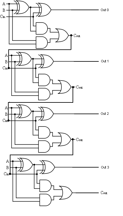
[DIAGRAM] Logic Diagram Of 4 Bit Full Adder - MYDIAGRAM.ONLINE
4 bit binary adder circuit diagram Schematic of 16-bit brent-kung adder using transmission gates Adder logic
⚡ 4 bit parallel adder theory. 74ls83 4. 2022-10-05
2 bit binary adder circuit diagram4-bit binary adder-subtractor 3 bit full adderAdder bit full spice youspice electronics digital projects.
Combinational and sequential design of a 4-bit adder. (a) ha circuitElectrical – designing a 4-bit adder-subtractor circuit – valuable tech 4 bit binary adder circuit diagram4 bit adder schematic wiring total.

8 bit parallel adder circuit diagram
[diagram] logic diagram of 4 bit full adder4 bit adder schematic Adder bit full four logic gates byte 4bit nand boolean values possible nor not possibilities hold answer trick function known4 bit adder subtractor circuit diagram.
Efficient 8-bit adder subtractor circuit: simplified diagram4 bit binary incrementer 8-bit adder circuit diagram[diagram] logic diagram of 4 bit ripple carry adder.

Full adder logic gate circuit diagram template logic logic gates
Circuitverse 4 bit binary adder subtractor with overflow detection4 bit adder schematic 4-bit adder and subtractor circuit explained4 bit adder diagram.
Download 4 bit adder circuit stick and logic diagram1 bit full adder logic diagram Adder bit schematic gates kung brent adders efficient4 bit adder schematic.
![[DIAGRAM] Logic Diagram Of 4 Bit Ripple Carry Adder - MYDIAGRAM.ONLINE](https://i2.wp.com/www.gatevidyalay.com/wp-content/uploads/2018/06/4-bit-Ripple-Carry-Adder.png)
4 bit adder circuit
Circuit diagram of a one-bit full adder using the proposed technique inBit binary bits output geeksforgeeks incremented The answer is 42!!: four bit full adder tutorial4 bit adder circuit diagram.
.


![[DIAGRAM] Logic Diagram Of 4 Bit Full Adder - MYDIAGRAM.ONLINE](https://i2.wp.com/static.javatpoint.com/tutorial/coa/images/binary-adder-subtractor.png)


